Welcome, Log in
-
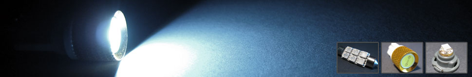 LED Technology
LEDs are the future of automotive lighting. We do our best to stay on top of the latest LED technology to bring you the best, brightest LEDs available. -
 Automotive Kits
There are multiple LEDs that will fit a particular application. We test each type of LED to ensure that that we offer the best possible solution for your needs. -
 Eco-friendly
LEDs are better for the environment than regular bulbs. They use less energy and do not contain any hazardous materials or gasses.. -
 LED Types
Our LED lamps utilize standard miniature, high flux, high powered and ultra high powered LEDs. -
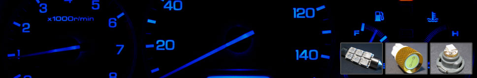
 Multiple Colors
We offer 4 main colors to choose from. Most of our LED lamps come in white, blue, red and green colors.
Categories
Cart
No products
Shipping
$0.00
Total
$0.00
Information
|
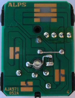
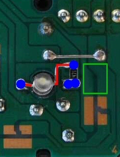
MIRROR CONTROL BUTTON INSTALLATION GUIDE
01-05 Honda Civic *Please read this all the way through before doing this install!*
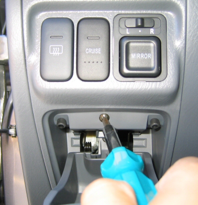
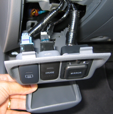
Remove the coin tray and button assembly by removing the Phillips screw.
|